

1. Overview
The NADC24 is a high-precision 24-bit Delta-Sigma analog-to-digital converter (ADC) developed by Nuvoton Technology, optimized for low-noise and high-resolution analog signal conversion. When paired with the Cortex-M0-based M031 microcontroller, it provides an accurate and cost-effective power measurement solution for single-phase power supplies (PSU). The system can monitor voltage, current, and power in real-time, while offering a user-friendly interface for configuration and calibration. Its compact and integrated design makes it suitable for energy monitoring, industrial control, and instrumentation applications.
2. Principles
The line voltage and current signals of the power supply are scaled down using a voltage divider and a current transformer, respectively. These analog signals are input to the NADC24 in differential mode. The integrated programmable gain amplifier (PGA) enhances small signals before they are digitized by the Delta-Sigma ADC core. The digitized data is transmitted to the M031 MCU via the SPI interface. Subsequently, the MCU calculates various power-related parameters and updates the display/UI in real-time.
3. Feature Description
Hardware components:
- NADC24 ADCProvides high-precision analog-to-digital conversion, with up to 22 effective number of bits (ENOB).
- M031 MicrocontrollerPerform signal processing and display functions.
- Voltage divider and current transformerReduce and isolate line voltage and current.
- SPI interfaceAchieve high-speed communication between NADC24 and M031.
Features:
- Supports up to 96 KSPS sampling rate.
- Integrated low-noise PGA with a gain range from 1 to 128.
- 8 single-ended or 4 differential input channels
- Internal Voltage Reference (1.2V/2.4V)
- Operating range: 2.7V – 3.6V, -40°C to 105°C
- Small package QFN32 or TSSOP20
3-1. Frequency Calculation
To calculate the line frequency, the system samples the zero-crossing points of the voltage waveform. The M031 measures the interval between zero-crossing points and calculates the frequency using the following method:

A digital low-pass filter is used to stabilize waveforms and prevent false crossings caused by noise.
3-2. Calculation of RMS Values of Voltage and Current
The RMS value is obtained by calculating the digitized waveform over a complete cycle:


Here, T represents the time period (commonly referred to as the accumulation period).
The PGA ensures sufficient dynamic range and resolution, enabling accurate RMS calculations even at low signal levels.
3-3. Active Power Calculation
Active power is the actual power consumed by the load. Its calculation formula is:

v(t) is the instantaneous voltage
i(t) is the instantaneous current
T is a period.
The sampled voltage and current waveforms must be time-aligned to ensure accurate multiplication.
3-4. Apparent Power Calculation
Apparent power represents the product of the RMS voltage and current.

This value includes both active power (real power) and reactive power components.
3-5. Power Factor Calculation
Power Factor (PF) is the ratio of active power to apparent power:

This metric reflects the efficiency of electricity usage. A power factor (PF) close to 1 indicates high electricity usage efficiency.
3-6. Fundamental wave and harmonic wave
Harmonic analysis involves applying Fast Fourier Transform (FFT) to voltage and current signals. The fundamental frequency (typically 50/60Hz) is separated, while higher frequency components are identified as harmonics.
- Total Harmonic Distortion (THD)Calculated as:

V1 is the RMS value of the fundamental voltage.
V2, V3, V4... are the root mean square (RMS) values of the second, third, fourth, and other harmonic voltages, respectively.
For current signals, the calculation formula for THD_I is:

I1 is the RMS value of the fundamental current.
V2, V3, V4... represent the effective values of the second, third, fourth, and other harmonic currents.
4. Data Processing and Access
4-1. Data Processing

4-2. Communication Protocol
This solution uses a communication protocol based on the Simple Sensor Interface (SSI) protocol. The baud rate for UART communication is 9600.
The protocol organizes all device communications into frames, with each frame containing a header byte, command and data length, command, data, and checksum.

4-3 Automatic Data Reporting
This table shows the format of automated report data.

5. Calibration
5.1 Environment

5.2 Calibration Steps

6. Test Report
| 800W average error rate | |||
| AC 100V | AC 230V | Direct current 240 volts | |
| Voltage error | 0.12% | 0.11% | 0.04% |
| Current error | 0.20% | 0.30% | 0.12% |
| Power error | 0.27% | 0.16% | 0.10% |
| 1300W Average Error Rate | |||
| AC 100 volts | AC 230V | Direct Current 240 Volts | |
| Voltage error | 0.21% | 0.03% | 0.07% |
| Current error | 0.18% | 0.09% | 0.17% |
| Power error | 0.38% | 0.15% | 0.17% |
| 2000W average error rate | |||
| Alternating current 100 volts | AC 230V | Direct current 240 volts | |
| Voltage error | 0.14% | 0.08% | 0.05% |
| Current error | 0.34% | 0.19% | 0.10% |
| Power error | 0.28% | 0.31% | 0.11% |
7. Conclusion
This power measurement solution is based on Nuvoton's NADC24 and M031 MCU, providing a highly integrated, accurate, and cost-effective system for real-time monitoring of single-phase power parameters. The NADC24's high effective number of bits (ENOB), integrated PGA, and versatile analog front-end simplify hardware design and reduce costs, while the M031 efficiently handles computational tasks. This solution supports frequency measurement, RMS calculation, power metrics, and harmonic analysis, making it ideal for industrial automation, smart meters, and embedded energy management systems.
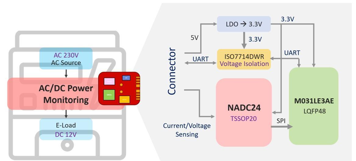
►场景应用图

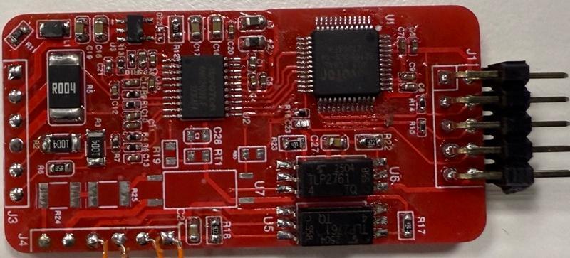
►展示板照片
►方案方块图
►核心技术优势
• High-Resolution Measurement Capability With a 24-bit Delta-Sigma architecture, the NADC24 offers up to 22 effective number of bits (ENOB), enabling the detection of minute voltage and current changes for extremely high measurement accuracy. • Built-in Low-Noise Programmable Gain Amplifier (PGA) Supports up to 128x gain, enhancing the measurement sensitivity of low-level signals without the need for additional analog front-end design. • Real-Time Power Calculation Capability Utilizes the M031 Cortex-M0 MCU for real-time calculations, including parameters such as frequency, voltage/current RMS, power factor, and fundamental/harmonic components, making it suitable for dynamic load monitoring. • High Integration and Low Bill of Materials (BOM) Cost The NADC24 integrates a voltage reference, temperature sensor, SPI communication, and multi-channel inputs, simplifying hardware design and layout requirements, effectively reducing PCB space and overall cost. • High-Speed and Stable Communication Interface High-speed SPI data transmission ensures precise data synchronization, making it ideal for applications requiring high sampling rates and high-frequency response. • Flexible Channel Configuration Supports 4 differential inputs or 8 single-ended inputs, allowing simultaneous monitoring of multiple signal sources such as voltage, current, and temperature.
►方案规格
This power measurement solution utilizes the Nuvoton NADC24, a 24-bit Delta-Sigma ADC with up to 22 effective number of bits (ENOB), paired with the NuMicro M031 Cortex-M0 MCU. It supports 4 differential inputs or 8 single-ended inputs, features a built-in temperature sensor, and offers PGA gain ranging from 1x to 128x. The system provides an adjustable output data rate from 15.625 SPS to 96 KSPS, includes an internal 1.2V/2.4V reference voltage (100 ppm/°C), and operates within a voltage range of 2.7V–3.6V and a temperature range of -40°C to 105°C. With an SPI communication interface, it features ±4kV ESD and ±4.4kV EFT protection, enabling precise real-time RMS, frequency, power factor, and harmonic analysis. It is suitable for applications such as power monitoring and smart metering.