

Introduction
AOZ18101DI is a current-limiting overvoltage protection electronic fuse (eFuse), primarily designed for applications requiring front-end protection on input lines. The absolute maximum rated voltage for both its VIN and VOUT terminals is 22V.This device features a programmable soft-start function, which effectively controls the inrush current of high-capacitance loads. Additionally, it includes input undervoltage lockout (UVLO), input overvoltage protection (OVP), and thermal shutdown protection (TSD) functions. An internal current limiting circuit is implemented to protect the power supply from large load current surges, and the current limit threshold can be configured using an external resistor.
The AOZ18101DI features a soft-start function that controls inrush current during startup. It also includes a Safe Operating Area (SOA) control function, which protects the device by preventing the internal Metal-Oxide-Semiconductor Field-Effect Transistor (MOSFET) from exceeding its safe operating area. During startup, the voltage at the VOUT pin rises linearly to the voltage at the VIN pin over a period of time. This rise time is referred to as the soft-start time, typically measured in milliseconds. The soft-start time (tON) can be programmed by connecting an external capacitor CSS to the SS pin, thereby controlling the inrush current. The following formula can be used to estimate the time required for the voltage to rise from 10% to 90% of its final value.

The unit of CSS is nanofarads (nF), and the unit of tON is milliseconds (ms).
During the soft-start period, there will be a relatively large voltage across the power switch. Additionally, a current ISW will flow through the switch to charge the output capacitor at the VOUT pin. Furthermore, there may also be load current flowing to the downstream system. The total current during the soft-start period is calculated as follows:

Under soft-start conditions, the power MOSFET acting as the power switch operates in linear mode, resulting in higher power dissipation. Since the soft-start ramp time is measured in milliseconds, the ability to handle this power dissipation largely depends on the Safe Operating Area (SOA) of the power MOSFET in linear mode and the good thermal performance of the package, specifically the thermal resistance RƟJC (junction-to-case thermal resistance).
The AOZ18101DI features current limiting control for SOA during soft start. Figure 1 illustrates an example of the current limit value as a percentage change of VOUT relative to VIN during startup. At the beginning of the startup, the current limit value is low due to the large voltage drop between VIN and VOUT, which helps to limit power dissipation. As VOUT increases during the startup process, the current limit value also increases to keep the power dissipation within the SOA range.
Figure 1The relationship between current limit and output voltage during startup
To ensure a successful startup without exceeding the safe operating area (SOA) of the internal MOSFET or reaching the current limit, it is necessary to correctly select the soft-start capacitor based on the output capacitance and load current. For guidance on how to properly select the CSS capacitor and COUT capacitor under various output load current conditions, please refer to Figure 2. In the figure, different colors indicate the recommended regions for CSS and COUT values corresponding to different load current levels. The recommended CSS values in the figure have both upper and lower limits.
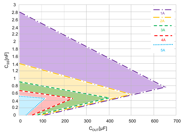
Figure 2Recommended CSS and COUT regions under different load current conditions
A soft-start time that is too long can cause the total energy during the soft-start period to exceed the Safe Operating Area (SOA), which may damage the device. To prevent SOA damage caused by high energy during startup, the load current, output capacitance, and startup time should be limited to the recommended area shown in Figure 2.
The recommended CSS region upper limit is determined by the Safe Operating Area (SOA). Exceeding the SOA during startup can damage the device. The lower limit of the recommended region is determined by the device's current limit control. If the current exceeds the current limit for 512 microseconds during soft start, the device will shut down to protect the internal MOSFET from damage. The current limit curve during soft start is shown in Figure 1.
Figure 3 shows the startup waveforms under the conditions of an input voltage of 14V, an output capacitance of 100 µF, and a load of 3A, using two different CSS capacitor values. Figure 3(a) illustrates the normal startup waveform when CSS = 0.78 nF, as the CSS capacitor is within the recommended range shown in Figure 3(c). Figure 3(b) depicts the abnormal startup waveform when CSS = 1.5 nF, as the CSS capacitor exceeds the recommended range shown in Figure 3(c). In this case, the energy during soft start is large enough to damage the device. During the next startup process, the device will fail. Figure 3(c) highlights the recommended regions for CSS and COUT under a load current of 3A using different colors.
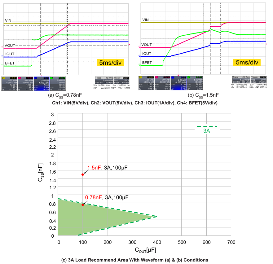
Figure 3Startup waveforms under different soft-start capacitors (VIN=14V, CIN=300µF, COUT=100µF, I_Load=3A)
Figure 4 illustrates the startup waveforms under the conditions of an input voltage Vin of 12V, a load resistance of 6Ω (i.e., a load current of 2A), and a soft-start capacitor CSS of 0.18nF, with varying output capacitor COUT values. Figure 4(a) shows the normal startup waveform when the output capacitor COUT = 100µF, as COUT is within the recommended range. Figure 4(b) shows the failed startup waveform when the output capacitor COUT = 680µF, as COUT exceeds the recommended range. Due to the larger COUT, the inrush current is also significant, and the current is limited by the current control function within 512 microseconds. The device is shut down and locked before completing the startup. Figure 4(c) uses different colors to display the recommended CSS and COUT range under the condition of a load current of 2A.
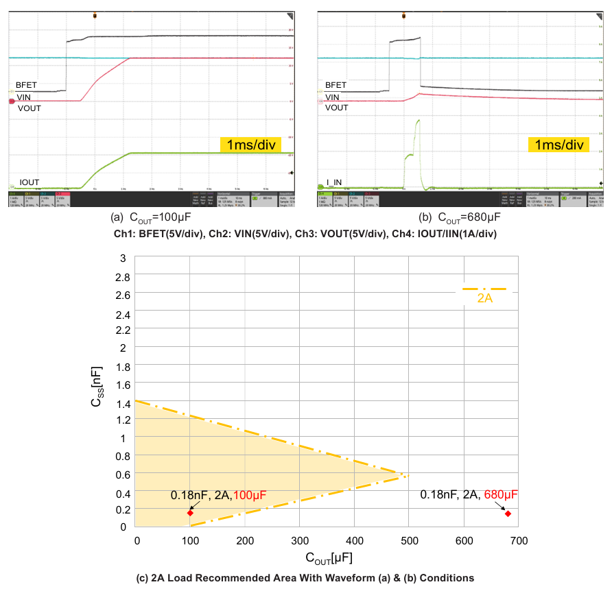
Figure 4 Rising waveforms under different Cout (VIN=12V, CIN=300µF, R_Load=6Ω, CSS=0.18nF)
Figure 5 illustrates the startup waveforms under different resistive load conditions when the input voltage Vin is 12V, the output capacitance is 570µF, and the soft-start capacitor CSS is 1nF. Figure 5(a) shows the normal startup waveform, as the parameters of CSS and COUT fall within the recommended range for a 1A load. Figure 5(b) shows the abnormal startup waveform, as the parameters of CSS and COUT exceed the recommended range for a 5A load. During the next startup process, the device may be damaged. Figure 5(c) uses different colors to indicate the recommended regions for 1A and 5A load conditions.
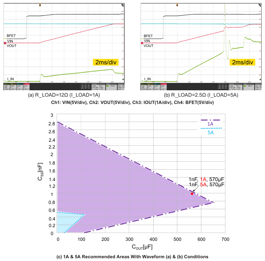
Figure 5 Rise waveforms under different loads (VIN=12V, CIN=300µF, COUT=570µF, CSS=1nF)
When evaluating the AOZ18101DI, it is recommended to use a purely resistive load instead of an electronic load. This is because an electronic load contains an internal controllable current source to simulate the load, which may interact with the AOZ18101DI's current limiting circuit and cause oscillations during startup.
Example: Input voltage VIN = 12V, output capacitance COUT = 100µF, load current = 3A. Since the load current is 3A, users can refer to Figure 2 to find the recommended soft-start capacitor value when the output capacitance COUT is 100µF. The recommended soft-start capacitor CSS value ranges from 0.05nF to 0.8nF. By substituting these CSS values into formula (1), users can calculate the soft-start time Ton to be between 1.35 milliseconds and 9.78 milliseconds.
In summary, there are three main parameters that determine the Safe Operating Area (SOA) range. The impact of each parameter on the SOA range has been tested and examples are provided. Figure 2 illustrates the SOA range guidelines for the AOZ18101DI. Additionally, a design tool is available to provide SOA guidance.