

Preface
本章節說明本文所使用的資料型態。
- 資料型態 :
每個 API 使用的資料型態在 Header file “DataType.h” 皆有定義與描述。
|
typedef |
Data types |
description |
|
SI_8 |
signed char |
Signed 8-bit |
|
SI_16 |
signed short |
Signed 16-bit |
|
SI_32 |
signed long |
Signed 32-bit |
|
SI_64 |
signed long long |
Signed 64-bit |
|
UI_8 |
unsigned char |
Unsigned 8-bit |
|
UI_16 |
unsigned short |
Unsigned 16-bit |
|
UI_32 |
unsigned long |
Unsigned 32-bit |
|
UI_64 |
unsigned long long |
Unsigned 64-bit |
|
SINT_T |
signed int |
Signed integer ( signed 32 bit ) |
|
UINT_T |
unsigned int |
Unsigned integer ( unsigned 32 bit ) |
|
CHAR_T |
char |
8-bit |
|
BOOL_T |
int |
Boolean value |
一. 概觀
1. 整體方塊圖
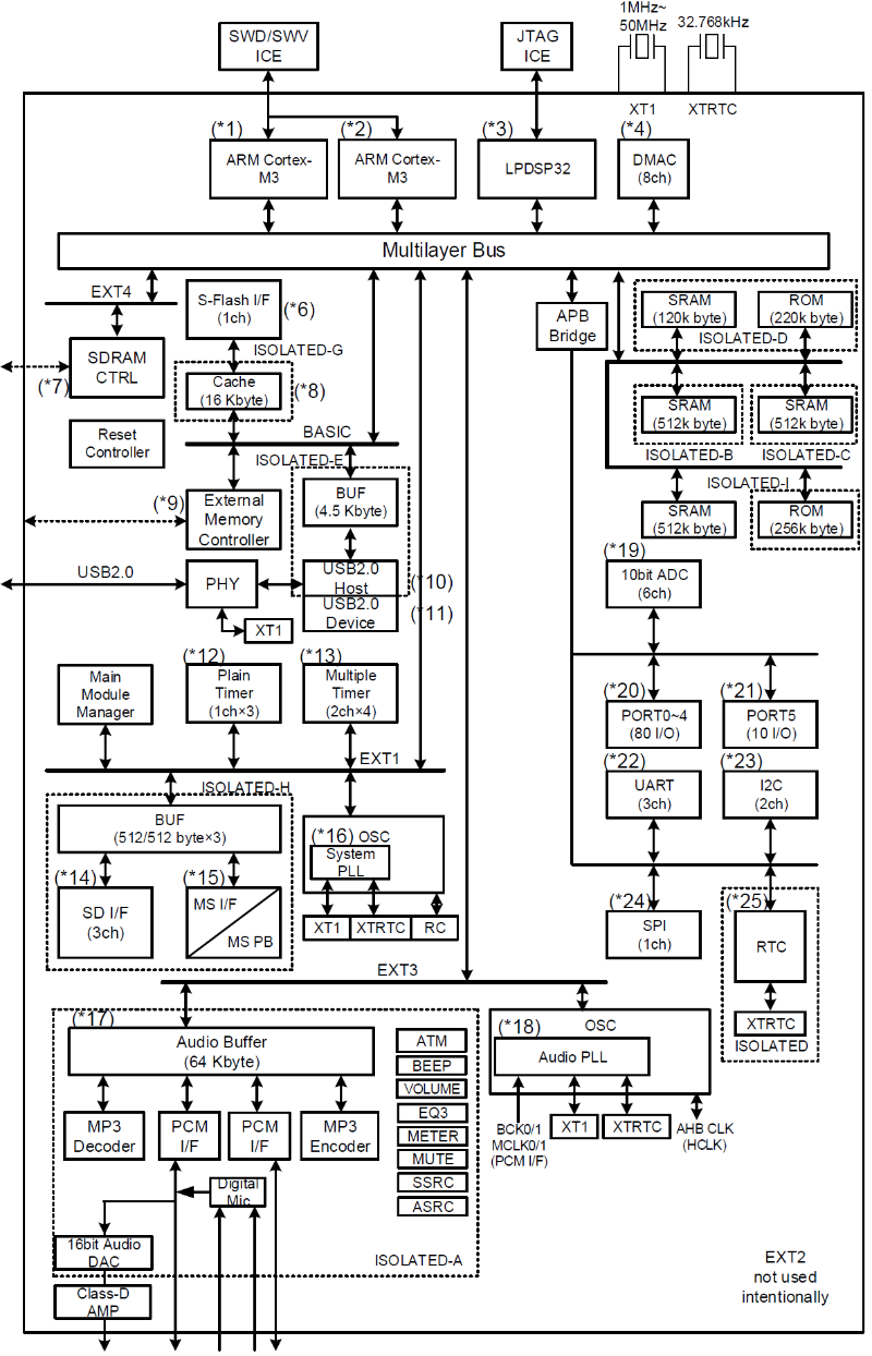
2.時脈系統方塊圖
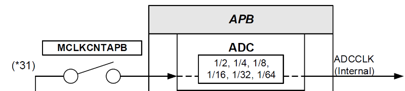
使用 function 控制獨立的 block 的 Clock ON/OFF ( e.g. : Module Clock Control APB Register: MCLKCNTAPB )
3.ADC Block 摘要
- ADC block 包含一個 AD 轉換器 (ADC) 可支援多達 6 Channel 的輸入.
- AD 轉換器有 10 bits ( 精確度 8 bit ) 的連續比較轉換器 ( successive comparison converter )
- 具有取樣保持電路 ( Sample hold circuit ) 設計,應用時無須額外的外部取樣保持電路。
- 具有 AD channel control function 透過 register setup 能夠 enables 多達 6 channel ADC 類比輸入。
- 使用 Channel 有二種方式 : 單一 Channel 信號源輸入,以及複數 Channels 的連續 AD 轉換。
- ADC block 有 4 個不同的 AD 轉換模式,程式根據應用選擇最適合的模式。
- 具有 ADC interrupt。AD 轉換器完成 AD 轉換後,會將已完成的 flag 通訊給 interrupt control block 當作 A/D converter interrupt factor. 接著就能產生 AD 轉換完成的 interrupt
- Power saving function 控制待機,支援 Software-standby 及 Hardware-standby
Table 18-1 Signal used with ADC
|
Signal |
Input/Output |
Function |
|
ADC Clock |
Input |
Clock for ADC. System clock is supplied |
|
ADC Standby |
Input |
For ADC standby control |
|
System Bus |
Bus |
For ADC control |
|
AN5 |
Input |
Input signal for ADC-Ch5 |
|
AN4 |
Input |
Input signal for ADC-Ch4 |
|
AN3 |
Input |
Input signal for ADC-Ch3 |
|
AN2 |
Input |
Input signal for ADC-Ch2 |
|
AN1 |
Input |
Input signal for ADC-Ch1 |
|
AN0 |
Input |
Input signal for ADC-Ch0 |
- 四種 ADC 轉換模式
- 單一模式 ( Single mode ) :
單一次執行單一 channel 的 AD 轉換。 - 連續單一模式( Continuous single mode ) :
重複執行單一 channel 的 AD 轉換。 - 掃描模式 ( Scan mode ) :
單一次執行已選定好的全部 channels 的 AD 轉換。 - 連續掃描模式 ( Continuous scan mode ) :
重複執行已選定好的全部 channels 的 AD 轉換。
- ADC 線路配置
ADC 配置的功能方塊圖。 見 圖 18-1
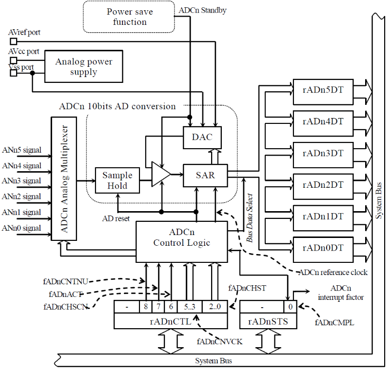
圖 18-1 ADC 配置
參訪 ON Semi. 網站取得更多資訊 :
System Functions User’s Manual : http://www.onsemi.com/pub/Collateral/AND9625-D.PDF
二. Application Interface
- Application Interface List
本節描述 LC823450 系列的 ADC Driver 的API :
|
Processing name |
Function name |
|
Driver initialization |
AdcDrInitialize |
|
Driver end |
AdcDrFinalize |
|
AD single conversion |
AdcDrSelectGet |
|
AD multi-conversion |
AdcDrMultiGet |
|
AD single conversion 10bit |
AdcDrSelectGet10Bit |
|
AD multi-conversion 10bit |
AdcDrMultiGet10Bit |
- Data Structures
ADC configuration type :
typedef struct t_AdcDrConfig{

    void    (*mAdcDrResetAndRelease)(void);             /* 初期化 */

    void    (*mAdcDrClkCtrl)(T_ADCDR_DEP_CLKCTRL Type); /* クロックコントロール */

    void    (*mAdcDrWait)(T_ADCDR_DEP_WAIT Type);       /* スタンバイ解除待ち時間実装 */
BOOL_T mUseDecoupCap; /* デカップリングコンデンサを使用するかどうか BGA以外はFALSE_T */
UI_32 mAdcDrRimp[ADCDR_CHANNEL_NUM]; /* 各チャンネルの入力インピーダンス(Ω) */
} T_ADCDR_CONFIG;
- Enumerations
typedef enum t_AdcDrResult{
ADCDR_SUCCESS = (0), /* OK */
ADCDR_ERR_PARAM = (-1), /* parameter error */
ADCDR_ERR_STATUS = (-2), /* not inisitalize */
ADCDR_ERR_SYSCLK_OVER = (-3),
/* SysClkがSPECオーバーしてしまう */
}T_ADCDR_RESULT;
- Functions format list
|
No. |
Functions format |
|
1 |
SINT_T AdcDrInitialize(UI_32* pWork, const T_ADCDR_CONFIG* pConfig); |
|
2 |
SINT_T AdcDrFinalize(void); |
|
3 |
SINT_T AdcDrSelectGet(UI_8 Ch, UI_8* pData, UI_32 SysClk); |
|
4 |
SINT_T AdcDrMultiGet(UI_8 Ch, UI_8* pData, UI_32 SysClk, UI_32 BufSize); |
|
5 |
SINT_T AdcDrSelectGet10Bit(UI_8 Ch, UI_16* pData, UI_32 SysClk); |
|
6 |
SINT_T AdcDrMultiGet10Bit(UI_8 Ch, UI_16* pData, UI_32 SysClk, UI_32 BufSize); |
- Functions Explanation list
|
No. |
Functions explanation |
|
1 |
The ADC driver is initialized according to information passed with pConfig. Please pass pWork the pointer of the 40 bytes memory that 4 bytes aligned. When callback and configuration mUseDecoupCap of mAdcDrResetAndRelease are used with TURE_T, callback processing mAdcDrClkCtrl and mAdcDrWait of the standby release are executed. |
|
2 |
The ADC driver is ended. The callback of mAdcDrClkCtrl and mAdcDrResetAndRelease and mAdcDrClkCtrl is executed. |
|
3 |
The analog to digital translation of the object channel selected with Ch is done. The value in which subordinate position 2bit is rounded down is stored in conversion result pData. When configuration mUseDecoupCap is used with FALSE_T, callback processing mAdcDrClkCtrl and mAdcDrWait of standby release/standby execution are executed. |
|
4 |
The analog to digital translation from Ch0 to the object channel is done. ( non-continuous scanning mode ) The value in which subordinate position 2bit is rounded down to each channel is stored in conversion result pData. The size of pData is input to BufSize. When configuration mUseDecoupCap is used with FALSE_T, callback processing mAdcDrClkCtrl and mAdcDrWait of standby release/standby execution are executed. |
|
5 |
The analog to digital translation of the object channel selected with Ch is done. When configuration mUseDecoupCap is used with FALSE_T, callback processing mAdcDrClkCtrl and mAdcDrWait of standby release/standby execution are executed.g mAdcDrClkCtrl and mAdcDrWait of standby release/standby execution are executed. |
|
6 |
The analog to digital translation from Ch0 to the object channel is done. (non-continuous scanning mode) The size of pData is input to BufSize. When configuration mUseDecoupCap is used with FALSE_T, callback processing mAdcDrClkCtrl and mAdcDrWait of standby release/standby execution are executed. |
三. Example Study
- EVTMD in project
Key events 讀取 AN5 上的信號 AD 轉換結果做按鍵識別。
- ADC initialization in function AdcInit.
|
~\Template_Project\MD\SYSMD\AdcDrDep\AdcDrDep.c |
/*============================================================

 関数名  :AdcInit

---------------------------------------------------------------

 機能    :Adc起動

===============================================================*/

SINT_T AdcInit(void)

{

    T_ADCDR_CONFIG Config;


    Config.mAdcDrResetAndRelease = AdcDrCallResetAndRelease;

    Config.mAdcDrClkCtrl = AdcDrCallClkCtrl;

    Config.mAdcDrWait = AdcDrCallBackWait;

    Config.mUseDecoupCap = FALSE_T;

    Config.mAdcDrRimp[0] = 10000;

    Config.mAdcDrRimp[1] = 10000;

    Config.mAdcDrRimp[2] = 10000;

    Config.mAdcDrRimp[3] = 10000;

    Config.mAdcDrRimp[4] = 300000;

    Config.mAdcDrRimp[5] = 10000;


    return(AdcDrInitialize(&AdcDrWork[0], &Config));

}- 在 function AdcKeyGet 按鍵識別應用使用了 ADC
|
~\Template_Project\MD\SYSMD\AdcDrDep\AdcDrDep.c |
/*===========================================================================
関数名 :AdcKeyGet
-----------------------------------------------------------------------------
機能 :ADキー値取得
引数 :UI_8 *pKeyType OUT タイプ
===========================================================================*/
SINT_T AdcKeyGet(UI_8 *pKey){
/* AD convert */
ret = AdcDrSelectGet(5, &key, PwrDrGetAPBClock()); 若使用 P17-004 OP-Morgan LC823450EVM Board, 透過按鈕可進行選單操作。
見 圖 4.1, 圖 4.2
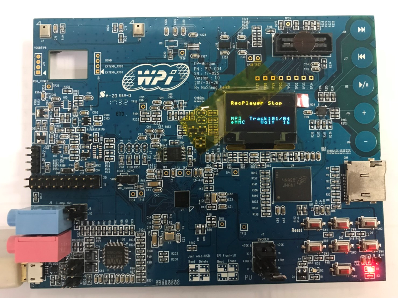
圖 4.1 P17-004 OP-Morgan LC823450EVM Board
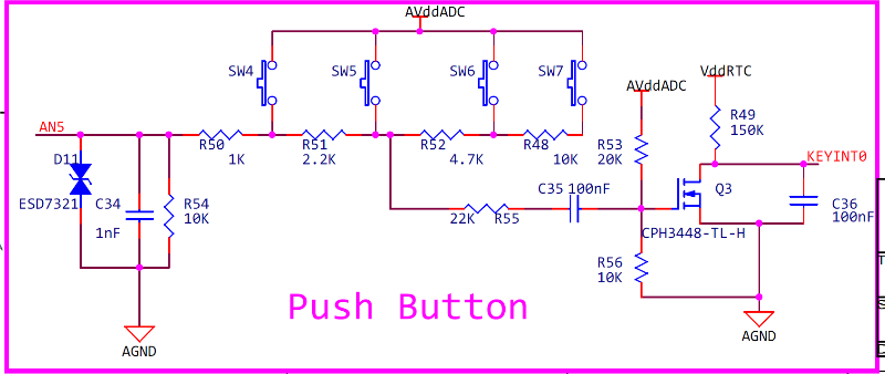
圖 4.2 P17-004 OP-Morgan LC823450EVM Board 按鍵線路
參考資料
- LC823450 IDE Toolchain package User manual 下載連結 URL :
https://www.onsemi.com/pub/Collateral/LC823450%20IDE%20MANUAL.ZIP - LC823450 IDE Import Manual Ver1.02 ( LC823450 IDE Import Manual_ver1.02.pdf )
- LC823450 IDE User Manual00 ( LC823450 IDE MANUAL.pdf )