

由於高通的SoC只有MIPI DSI 的介面.如果要外接LVDS 的大尺寸LCD panel.則需要搭配MIPI轉LVDS的bridge IC.
以驅動的porting角度可以直接用DRM 的bridge IC 的方式,另一種就是把Bridge IC當成MIPI 的LCD panel來移植
驅動.由於以bridge IC 的方式要修改的部份相對較多以點LCD panel 的方式相對容易.
本文是採用點LCD panel 的方式來做驅動的porting.
在QCS610 的device tree去掛載mipi的1080p 的LCD panel.
qcs610-iot.dtsi加入
&dsi_panel_ili988c_720p_vid_display {
qcom,dsi-display-active;
qcom,display-type = "primary";
};
依照LVDS panel的spec填寫高通提供的
80-NH713-1 YY DSI TIMING PARAMETERS User Interactive Spreadsheet
以得到PHY與相關的參數設定值修改在dsi-panel-ili988c-dual-video.dtsi與sm6150-sde-display.dtsi相應的設定值
由於無需用到DSI command與TC358775需要有外部的clock輸入
所以要將
//qcom,mdss-dsi-lp11-init; ------>disable
qcom,mdss-dsi-force-clock-lane-hs; ------>Add
否則LCD panel 的畫面會有偏移與不穩定的狀況
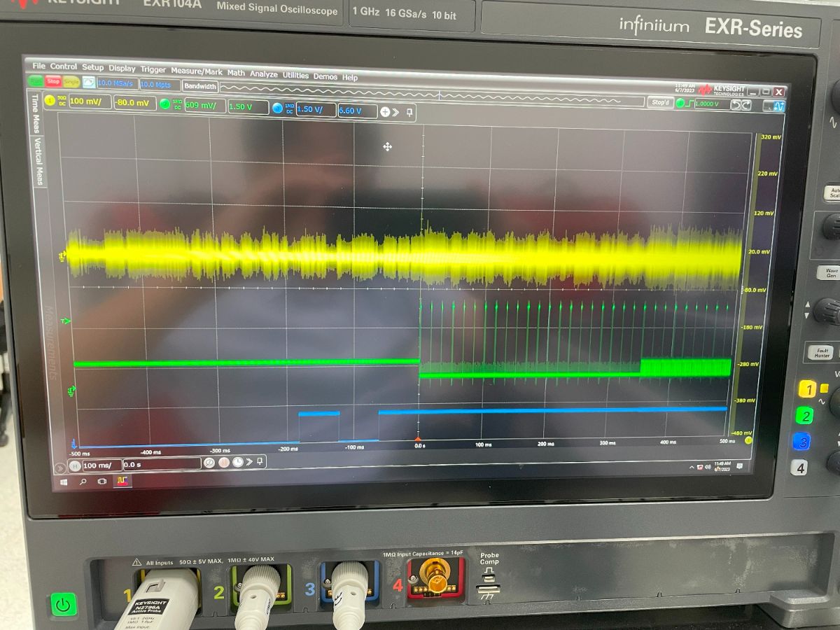
以上為正確的clock波形圖
黃色為clock 訊號
綠色為data 訊號
藍色為reset 訊號
在Toshiba端的register 相關設定請參考以下的大大通博文:
Toshiba TC358775XBG初始化程式碼工具教學
https://www.wpgdadatong.com/blog/detail/46466
在QCS610與TC358775間的I2C 溝通在Yocto系統可以使用
I2c tool中的i2ctransfer 來做read/write的動作
在/apps_proc/poky/qti-conf/local.conf
加入以下的設定:
IMAGE_INSTALL_append = " i2c-tools"
加入以上的設定後再重新編譯image
即可以使用I2C tools
TC358775的i2C address為0xf
以下是寫入到TC358775的Shell Script的部分的code.
#!/bin/sh
#
setenforce 0
mount -o remount,rw /
#TC358774/75XBG DSI Basic Parameters. Following 10 setting should be pefromed in LP mode
#01 3C 08 00 06 00
i2ctransfer -f -y 2 w6@0x0f 0x01 0x3c 0x08 0x00 0x06 0x00
sleep 1
#01 14 05 00 00 00
i2ctransfer -f -y 2 w6@0x0f 0x01 0x14 0x05 0x00 0x00 0x00
sleep 1
#01 64 07 00 00 00
i2ctransfer -f -y 2 w6@0x0f 0x01 0x64 0x15 0x00 0x00 0x00
sleep 1
#01 68 07 00 00 00
i2ctransfer -f -y 2 w6@0x0f 0x01 0x68 0x15 0x00 0x00 0x00
sleep 1
#01 6C 07 00 00 00
i2ctransfer -f -y 2 w6@0x0f 0x01 0x6c 0x15 0x00 0x00 0x00
sleep 1
#01 70 07 00 00 00
i2ctransfer -f -y 2 w6@0x0f 0x01 0x70 0x15 0x00 0x00 0x00
sleep 1
#01 34 1F 00 00 00
i2ctransfer -f -y 2 w6@0x0f 0x01 0x34 0x1f 0x00 0x00 0x00
sleep 1
#02 10 1F 00 00 00
i2ctransfer -f -y 2 w6@0x0f 0x02 0x10 0x1f 0x00 0x00 0x00
sleep 1
#01 04 01 00 00 00
i2ctransfer -f -y 2 w6@0x0f 0x01 0x04 0x01 0x00 0x00 0x00
sleep 1
#02 04 01 00 00 00
i2ctransfer -f -y 2 w6@0x0f 0x02 0x04 0x01 0x00 0x00 0x00
#TC358774/75XBG Timing and mode setting
#04 50 20 01 F0 3F
i2ctransfer -f -y 2 w6@0x0f 0x04 0x50 0x20 0x01 0xd0 0x1d
sleep 1
#04 54 14 00 50 00
i2ctransfer -f -y 2 w6@0x0f 0x04 0x54 0x2c 0x00 0x94 0x00
sleep 1
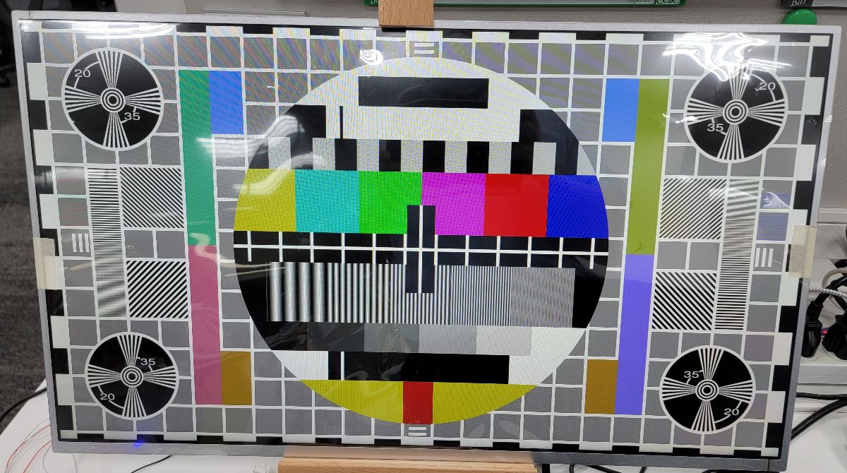
以下為經由I2C 設定後正常顯示測試pattern的畫面
參考文件:
- 80-NH713-1 DSI Timing Parameters User Interactive Spreadsheet
- 80-PG596-83_REV_B_SM6150_Linux_Android_Display_Overview
- 80-PG596-84_REV_A_SM6150_Linux_Android_Display_Panel_Bringup_Guide
- Thundercomm TurboX™ C610 Open Kit Display Panel Bringup Guide
高通的mdss-dsi-panel的device tree 參數說明
Q&A:
問題一:
如果在Android系統應該如何自動執行i2C來設定TC358775的暫存器?
在Android系統可以另外執行i2C的driver或是在init.rc中去自動執行Script
問題二:
如何判斷i2C寫入到TC358775的暫存器的值是正確的?
可以i2ctransfer的command讀取暫存器的值來判斷
例如讀取ID REG 0x05 0x80 的值
i2ctransfer -y 2 w2@0x0f 0x05 0x80 r4
0x00 0x00 0x75 0x00