

一、簡介
由於現代人每天的忙碌生活中,其娛樂的部分也是生活上壓力的調節劑, 隨著電玩產業興盛,一些電玩周邊的周邊商品也漸漸開始要求效能與貼近操作真實感。
本方案 Gaming Controller 藉由 NXP LPC55平台進行開發,平台 MCU 為 ARM Cotex M33 核心 ( 150 MHz ) 帶高速 USB 與 Audio 的傳輸架構,藉由方案架構即可邊玩遊戲之餘,還可同時於 Controller 端聆聽音樂或遊戲時的音效。
方案 Gaming Controller 模組板規劃了 15 個 button 與 6 組 16 bit ADC 作為輸入介面,本文章針對模組板輸入介面操作方式與測試軟體做介紹
二、 模組板輸入介面:
2.1 基本輸入單元 ( 如圖 1 )
GPIO: Left、Right、Down、Up、X、Y、A、B、LB、RB、XE、BACK、START、Left Joystick button、Right Joystick button
ADC:Left Joystick ( X、Y 軸 )、Right Joystick ( X、Y 軸 )、RT、LT
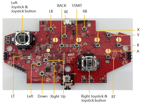
圖 1 Main Board ( LPC5528 )
2.2 Connector 單元 ( 如圖 2 )
Vibration Motor Power Select ( CON1、CON2 ):Pin 1、2 配置短路 Pin 使 Vibration Motor 為 1.8 V
Vibration Motor Output ( J9、J10 ):Vibration Motor 配置端口
SWD Connector ( J1 ):GND、Reset、SWCLK、SWDIO、1.8 V ( 由左而右 )
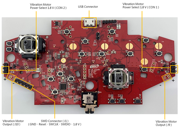
圖 2 Main Board ( LPC5528 ) 周邊 Connector
三、Controller 測試軟體:
3.1 取得 Game Controller Tester
以 Win10 作業系統為例,於 Windows 點選開始 , 尋找 Microsoft Store並執行,如圖 3
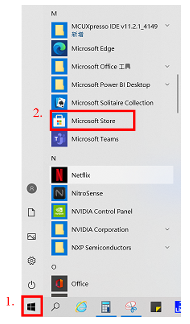
圖 3 搜尋 Microsoft Store
3.2 尋找 Game Controller Tester
於尋找框中搜尋 Game Controller Tester,如圖 4

圖 4 搜尋 Game Controller Tester
3.3 下載與安裝 Game Controller Tester
搜尋完畢後出現應用程式,點選 Game Controller Tester,如圖 5。
點選下載並安裝,如圖 6。
* 本案例已安裝完成,因此顯示為啟動
* Game Controller Tester 為免費軟體
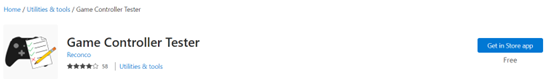
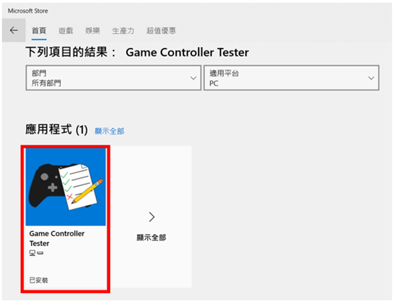
圖 5 點選 Game Controller Tester
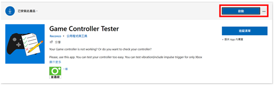
圖 6 下載 Game Controller Tester
3.4 執行 Game Controller Tester
當模組板未與 PC 端連結時如圖 7
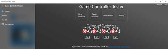
圖 7 模組板未與 PC 端連結
四、Controller 測試步驟
4.1 將 USB Cable 與模組板 USB Connector 連結,如圖 8
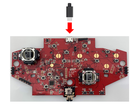
圖 8 USB Cable 與模組板 USB Connector
4.2 當模組板與 PC 端連結時時如圖 9
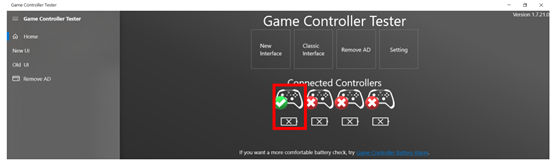
圖 9 模組板與 PC 端連結
4.3 點選 Start Testing,選擇檢視 Controller 1,如圖 10
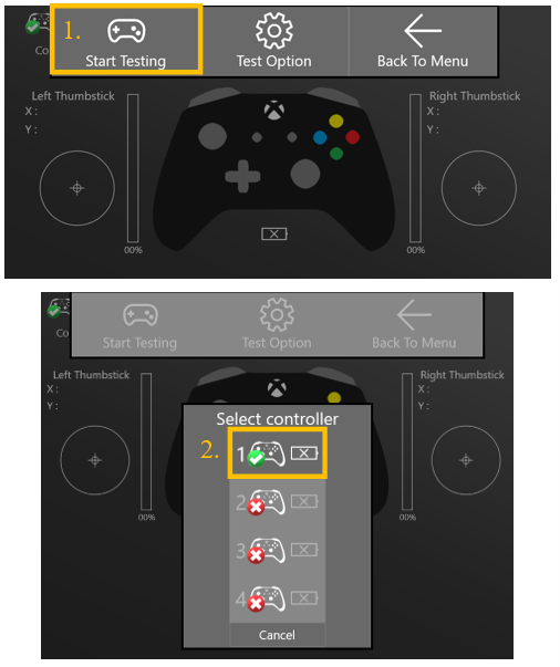
圖 10 選擇 Controller 1
4.4 完成設定後即可開始檢視控制現況,當 Controller 下達指令後,Game Controller Tester 將對應指令值呈現,如圖 11 ~ 15
* Left & Right Joystick 因結構問題有可能在操作後,回彈到原點時未完整規定位,導致 Game Controller Tester 上顯示的 X、Y 軸數值未歸 0,此時需稍微撥動 Left & Right Joystick 結構,使其回歸定位即可將數值歸 0
* 點擊 LB、RB 時會驅動 Vibration Motor
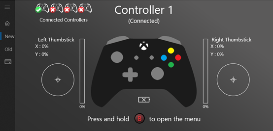
圖 11 Game Controller Tester 介面
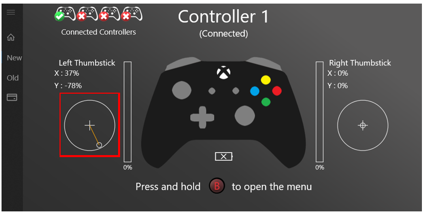
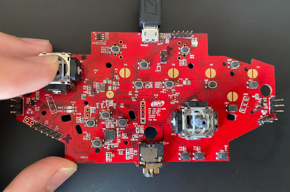
圖 12 搖桿帽 ( LX、LY ) 操作狀況
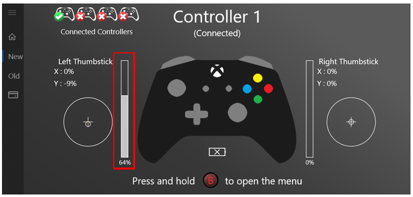
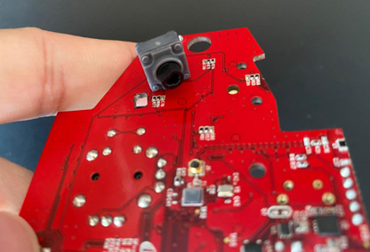
圖 13 LT 操作狀況
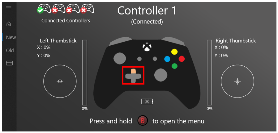
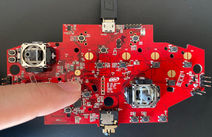
圖 14 上、下、左、右按鍵操作狀況
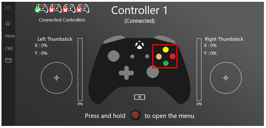
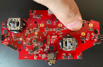
圖 15 X、Y、A、B 按鍵操作狀況